Walthers model 933-2907
Gas Storage Tank
First off, let me apologize for the photography; all the pictures were taken with my cell phone under less-than-ideal lighting. Second, these directions may sound a little over-simplified, but I figure every hint possible is a good aid toward a good model - so bear with me and read on; you may get a useful tip or two anyway.
Walthers Gas Storage Tank (catalog number 933-2907) is an HO scale model of an urban moonolith used to store coal gas, a by-product of the heating of coal in air-tight ovens called retorts. Coal gas was used to light city streetlamps - and in the early days, homes and businesses - as well as to provide heating and cooking fuel for homes and businesses as well.
One could tell how much gas was in one of these behemoths by how many sections, or lifts were inflated. As gas filled the holder, the top lift would rise; when it was fully inflated, a curved-under lip around the bottom edge would interlock with a curved-over lip around the top edge of the lift below, engaging the second lift and causing it to rise as well.There was water in between the interlocking pieces to prevent gas from leaking out.
Overnight, the gas holder would be filled in anticipation of heavy gas useage in the morning when people would wake up to take showers or baths and to cook breakfast in preparation for going to work or school. During that time, the level of gas in the holder would drop and the lifts, beginning with the top one, would fall back to earth. Gas would be generated during the day and the lifts would once again rise until the holder was full; in the evening the ueeage would once again be heavy and the lifts would fall when people returned home and started cooking and heating their homes. The process was repeated 24 hours a day.
Coal gas fell out of fashion with the ready availability of natural gas in the 1980s and 1990s; the last coal gas plant closed in the 1990s.
As of this writing (March 28, 2020) Walthers' Gas Storage Tank is still available in N scale (catalog number 933-3819) as well as HO scale.
Before we begin, remember a few basic modeling tips:
- Always use a sharp hobby knife or a pair of sprue cutters.
- Always trim flash and sprue nubs from model pieces
- Use glue sparingly - don't use so much that it oozes through joints and mars the model surface
Note that, because of the curvature of the handrail castings, the sprue arms holding the handrails are formed in such a way that laying the sprue sheet flat isn't possible, and using a hobby knife to cut the handrails free will probably result in broken handrails; it is therefore recommended that sprue cutters be used for this oepration. Sprue cutters may be obtained from Micro-Mark.
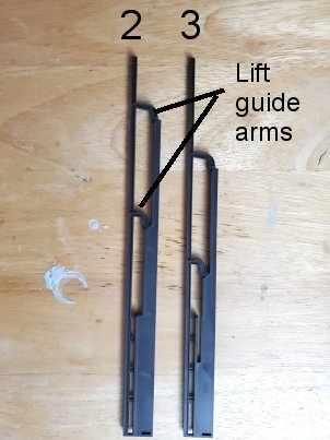
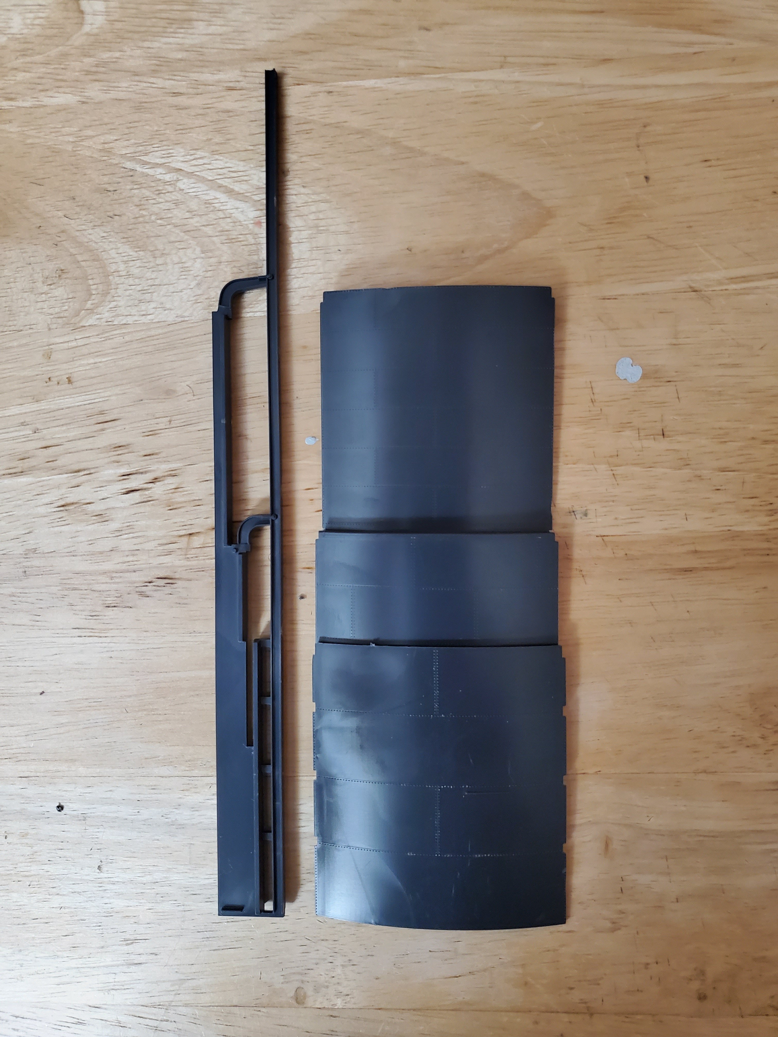
To begin with, the model may be built in either of two ways. with a tall upright support (part number 2) to represent the holder with all three lifts inflated, or a shorter upright support (part number 3) to represent a holder with the center lift partially inflated. Actually, both pieces are the same height; the difference is in the location of the lift guide arms:
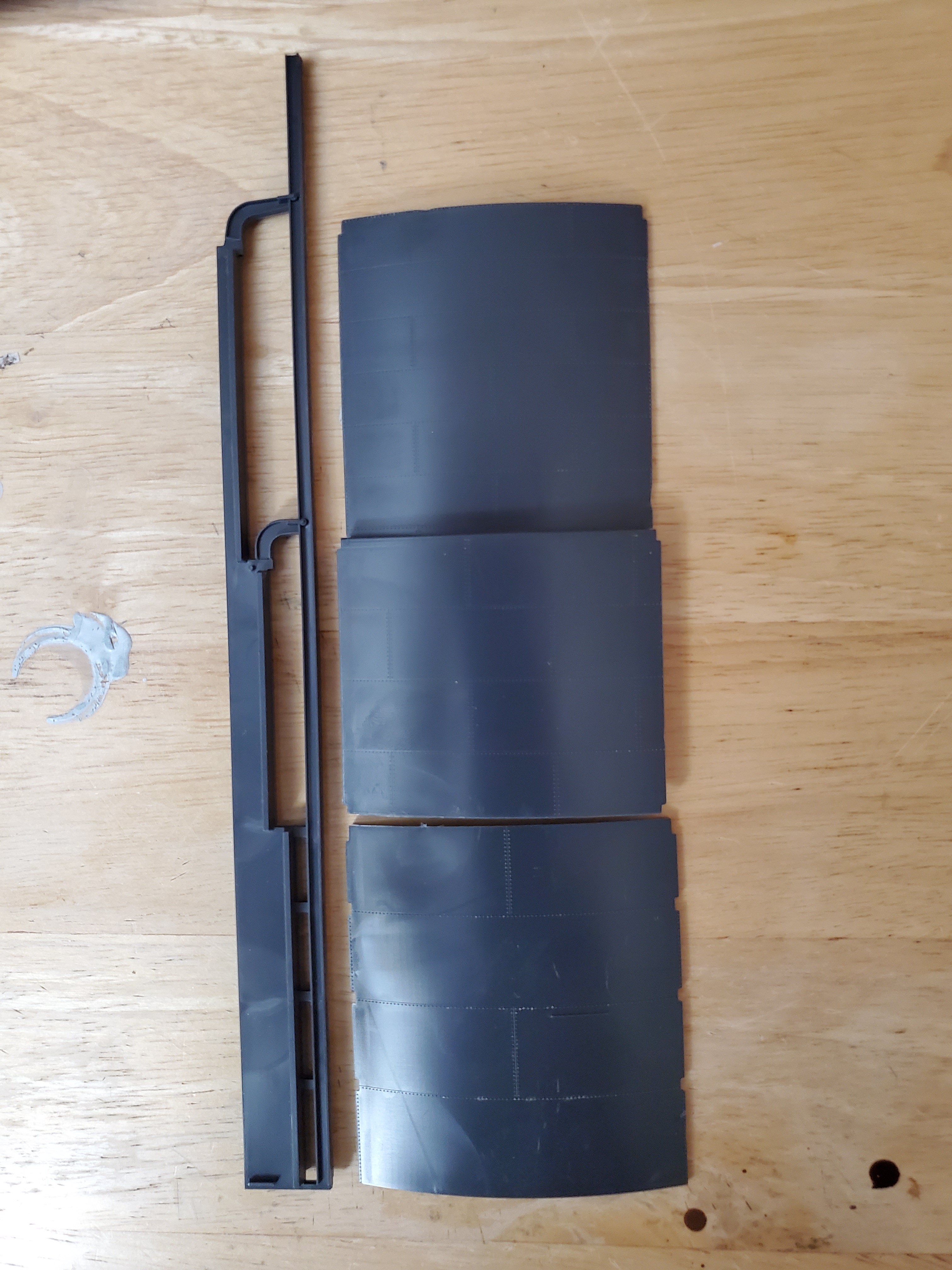
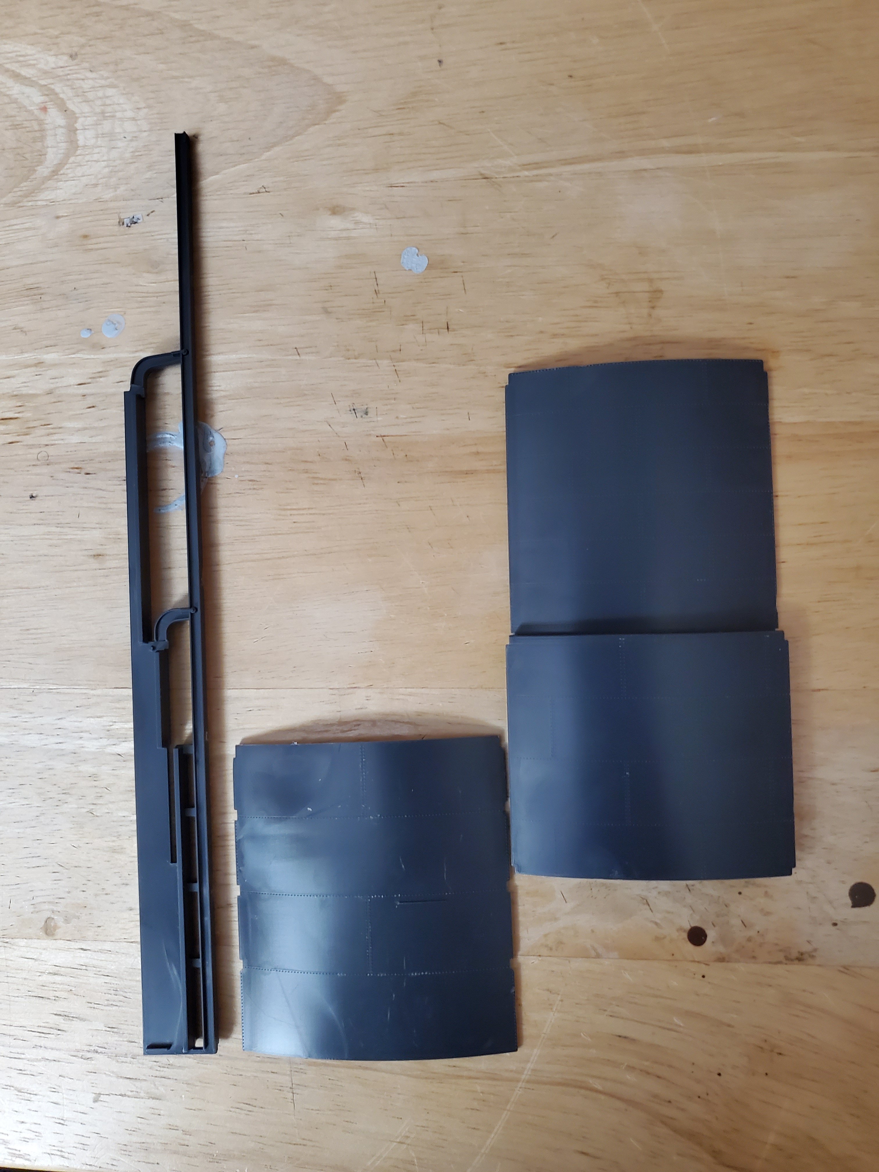
The photos below show the relationship between the uprights and the lift sections. In all three photos the bottom piece is part number 5 and the top piece is part number 7. The leftmost photo shows the arrangement for the use of the taller upright. The center photo shows the use of the shorter uprught and the alignment of part 5 and part 7 to achieve the "deflated" look; the rightmost photo shows part 5 and part 7 properly nested for this purpose.
|
|
|
Regarding parts 5 and 7: be aware that there are 10 of each part; however there is also one (1) part 6 that is used in place of one of the parts 5, so when you're done assembling the cylinder you will have an extra part 5.
|
As the instructions indicate, we begin with part 6 , a lower segment with a ridge located halfway up from the bottom and to the right of center (see photo, right). It is important to locate this segment correctly in order to be able to place the steps later on.
|
|
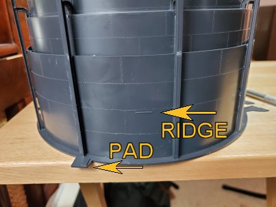
Apply glue to both sides of the foot of two uprights (parts 3) beneath the ridges. Also apply glue along the outsie of the ridge on the base. Next, insert the foot of one upright into the slot in the base on the pad, and place the left side of part 6 into the right side of the upright so that the notches in part 6 engage the "nubs" in the upright (part 3). Now place the second upright in the next slot to the right, engaging the slots in the right side of part 6 with the "nubs" on the upright (part 3). Finally, glue part 7, the lift sections, above Part 6, engaging the slots in part 7 with the lift guide arms on the uprights (parts 3).
Continue this process, using parts 5 in place of part 6, until the cylinder is complete.
Once the cylinder is complete and has thoroughly dried and may be handled, it is time to apply the walkways (parts 19 (1 piece) and 20 (2 pieces)). Part 19 has a platform that lines up directly over the pad on the base.
|
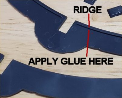
Walkway parts 19 and 20 must slide down over the uprights because the orientation of the rectangular slots will not permit merely sliding the parts into place horizontally. There is a ridge along the inner circumference of the bottoms of parts 19 and 20; apply glue toward the outside of the ridge, as shown in the photo to the left.
Slide the parts into position to rest on top of lower segments parts 5 and 6. |
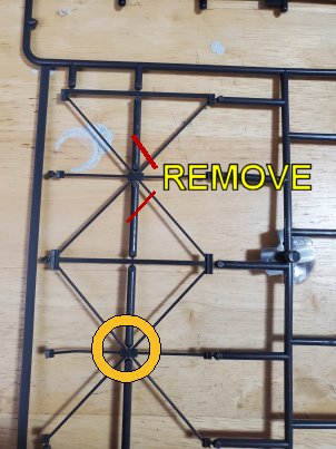
Next is the "x-bracing", or lateral bracing. When cutting these pieces from the sprues, be sure to remove the chunky vertical pieces between the diagobnal bracing sections. See photo to the right.
|
|
When applying the X-bracing (Parts 4), be sure to align the top of the bracing with the top of the uprights (Parts 3). .When properly aligned, the tab at the top of part 4 will fall into the notch at the top of part 3.
Simply follow the directions for the rest of the assembly of the model. A WORD OF WARNING, however: be extremely careful handling the srue sections of molded parts during the preceding steps; otherwise you will, as I did, wind up with many pieces of broken hand railing.
When applying the handrails (parts 14, 15 and 16) don't try to apply glue to the railings; instead, apply a dab of glue in the notches on the walkways (parts 19 and 20), then apply the section of hamdrail.